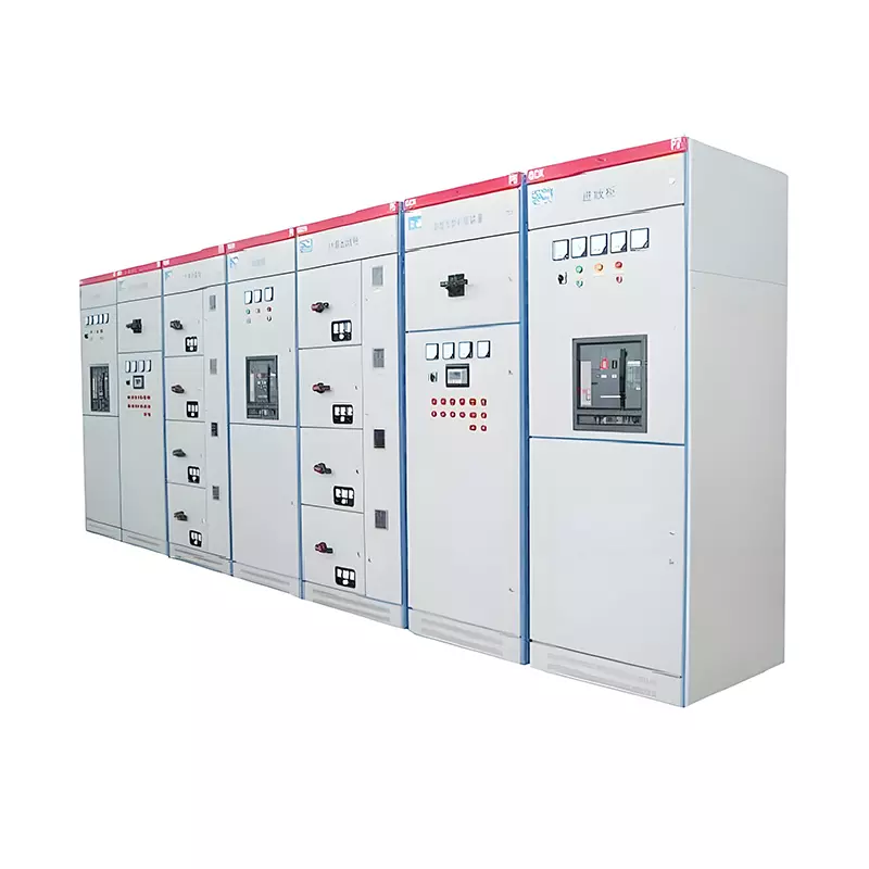
GCK low-voltage withdrawable switchgear
Usage conditions
The ambient air temperature shall not exceed +40℃, nor be lower than -5℃, and the average temperature within 24 hours shall not exceed +35℃
Atmospheric conditions: Clean air, relative humidity not exceeding 50% at the maximum temperature of +40° C. Higher relative humidity is allowed at lower temperatures, for example, 90% at +20 ° C. However, it should be taken into account that due to temperature changes, condensation of humidity may occur occasionally.
The altitude does not exceed 2000 meters.
This device is suitable for transportation and storage processes within the temperature range of -25° C to +55° C, and can reach +70 ° C for a short period of time (not exceeding 24 hours). It should not suffer any irreparable damage during installation at these extreme temperatures, and it should be able to operate normally under normal conditions.
If the above usage conditions cannot be met, the user and the manufacturer should negotiate a solution.
Electrical performance
● Cabinet structure
The basic frame of the switch cabinet is made of our factory's standard CF28 profile, and it is assembled by combining 8.8 grade high-strength self-tapping screws, featuring excellent mechanical properties. The C-shaped profile is made by bending steel plates with installation holes of E=25mm as the modulus. The structural components of the frame are all treated with galvanization or powder coating. According to the requirements of the changes in the primary circuit scheme, necessary doors, cover plates, partition installation supports, busbars, functional units and other components are added to form a complete switch cabinet.
The external dimensions of the frame and the components vary according to the module. Therefore, the structural parts of this device have high universality and strong applicability. Only a few external dimensions and a small amount of length variation can meet the needs of scheme changes. It can also meet the requirements of top-in top-out, bottomin bottomout, top-in bottomout and bottomin top-out for cables.
Both the front and back of this device are in the form of door opening, which is convenient for maintenance at the back of the cabinet. Each cabinet is divided into three rooms, namely the horizontal busbar room (at the top of the cabinet), the functional unit room (at the front of the cabinet), and the cable room (at the back of the cabinet)
The compartments are separated from each other by steel plates, and both the upper and lower small compartments are isolated by metal plates with ventilation holes, effectively preventing accidents caused by arc flying due to component failure and short circuits in busbars or other lines.
● Functional Unit
● Functional units are classified by their uses as follows: functional units for power distribution centers (IP) and functional units for electric control centers (MCC).
● Functional units are classified by installation method into drawer-type distribution cabinets and fixed compartment-type distribution cabinets.
The functional units are designed as fixed compartments. The functional units can be increased arbitrarily with a height of 100mm as the base and a height of 200mm as the modulus.
Related Products
Related Blog

High efficiency, energy conservation, safety and reliability - Yimuda low-voltage withdrawable switchgear helps upgrade the global power system
The global demand for low-voltage distribution cabinets has soared: Chinese manufacturers are leading technological innovation and export growth
High-efficiency and energy-saving power distribution cabinets are selling well worldwide, helping enterprises upgrade their power management
Yimuda Launches a New Generation of Modular Terminal Combination Electrical Appliances to Facilitate the Upgrade of Global Power Systems
Intelligent distribution box solution: Providing safe and efficient power management for global customers